Number Of Slots Per Pole Per Phase Formula
- Number Of Slots Per Pole Per Phase Formula Cost
- Number Of Slots Per Pole Per Phase Formula Per
- Number Of Slots Per Pole Per Phase Formula Calculator
- Number Of Slots Per Pole Per Phase Formula Sheet
Definition
Distribution factor is defined as the ratio of phasor sum of coil emfs to the arithmetic sum of coil emfs. It is also known as Belt or Breadth factor and denoted by kd.
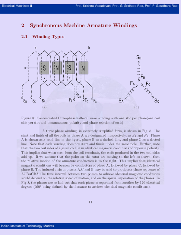
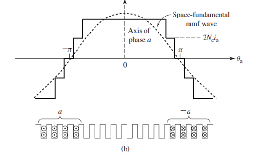
A 200 KW, 600 V DC, 6 pole dc shunt generator has an armature with 18 slots per pole. It has a simple lap winding with 4 conductors per slot. The armature and shunt field winding has resistance of 0.1 Ω and 50 Ω respectively. The flux per pole is 0.07 Wb. Calculate the speed at which it is to be driven for rated load operation. If the number of slots per pole per phase 𝒒𝒒= 𝑺𝑺 𝒎𝒎𝑷𝑷. Is an integer, then the winding is called an. Integral-slot winding in case the number of slots per pole per phase, q is not an integer, the winding is called. Fractional-slot winding. For example a 3-phase winding with 36 slots and 4 poles is an integral slot. A 30 amp two pole breaker allows up to 30 amps per leg or phase to conduct in fact provided a 'total' of 60 amps. However, 220 volt devices require the rated amperage for each leg. The number of slots should be selected to give an integral number of slots per pole per phase. The stator slot pitch at the air gap surface should be between 1.5 to 2.5 cm. Stator slot pitch at the air gap surface = τ.
In electrical machine, armature winding is distributed in the slots. It is not concentrated in a single slot. Therefore the total emf generated across the armature terminal is the phasor sum of emfs induced in individual coils. If these coils were concentrated, then the total induced emf would have been arithmetic sum of induced emf in a single turn of coil. Thus to find the factor of distribution or the degree of distribution of coils, distribution factor has been defined as the ratio of emf induced in distributed winding to the emf induced in concentrated winding. This definition of distribution factor is same stated earlier in the post.

Calculation of Distribution Factor
To get a general expression or formula of distribution factor, let us assume a 2 pole, 3 phase electrical machine having a total of 18 slots in its stator. These slots are distributed along the periphery of stator in 2 pole pitches. Therefore the angle between any two consecutive slots will be equal to 20 degree (2×180 / 18 = 20). This angle between two consecutive slots is called Angular Slot Pitch. It is in electrical degree not in mechanical degree.
Thus angular slot pitch for our example is 20 degree. The number of slots per pole per phase will be 3 [(18/2)/3 = 3]. This means that a particular phase will consists of three coils distributed in three slots under a single pole. This is shown in figure below.
In the above figure it can be seen that, coils are distributed in slot number 1,2,3 and 10,11,12. It can also be observed that, coil sides are connected in series in such a way that emf induced in coil side at 1 and 10 are additive. This means, if E1 and E10 are the emf induced in respective coil sides then the total emf induced will be E1+E10. Similarly, if the emf induced in coil sides 2 and 11 are E2 & E11, then the total emf in coil 2-11 is given as arithmetic sum of E2 and E11.

Thus the total emf at the coil terminal A & B is the phasor sum of (E1+E10), (E2+E11) and (E3+E12). Let us assume (E1+E10) as reference phasor and draw the phasor diagram of the above three emf to get the total emf available at terminal AB.
In the above phasor, ab represents (E1+E10). Since the slots are displaced from each other by angular slot pitch of γ (in our example, it is 20 degree), this means the emf induced in coil 2-11 will be displace by an angle of γ from reference phasor ab. This is shown by ‘bc’ in above phasor. Similarly, ‘cd’ represents the emf induced in coil 3-12 and is displaced by reference phasor by and angle of 2γ.
Thus the total emf across terminals AB of coil will be the phasor sum of ab, bd and cd which is equal to ‘ad’. Let us now calculate this phasor sum.
Since ab, bc and cd are lying in stator slot, therefore their perpendicular bisector must meet at the centre of the circle. Let us now draw perpendicular bisector oe and of on ab and ad respectively as shown in above figure. In general, the angle aob should be equal to angular slot pitch γ, angle aod equal to qγ and angle aof equal to (qγ/2) where q is number of slots per pole per phase.
In right angled triangle aoe,
Sin (γ/2) = ae / oa
ae = oaSin(γ/2)
Thus, ab = 2oaSin(γ/2) as oe is perpendicular bisector of ab.
Therefore, if the coil were concentrated then the emf across coil terminal AB would have been arithmetic sum of emf. This is given as
Emf per coil = Number of slots per pole per phase x 2oeSin(γ/2)
= 2q(oa)Sin(γ/2)
Now, in right angled triangle aof,
Sin(qγ/2) = af / oa
af = (oa)Sin(qγ/2)
Hence the resultant emf ad equal to the phasor sum of ab, bc and cd is given as
ad = 2(oa)Sin(qγ/2)
Therefore as per the definition of distribution factor,
Kd = Phasor Sum of Coil emf / Arithmetic sum of coil emf
= ad / q ab
= [2(oa)Sin(qγ/2)] / [2q(oa)Sin(γ/2)]
= Sin(qγ/2) / qSin(γ/2)
Thus the formula for distribution factor is given as below.
Number Of Slots Per Pole Per Phase Formula Cost
where q is number of slots per pole per phase and γ is angular slot pitch.
Effect of Harmonics on Distribution Factor
In electrical machine, every effort is made to make the magnetic flux density wave sinusoidal in space. But practically, it is never distributed sinusoidally in space. Rather it contains various harmonics. Out of various harmonics, third harmonic is the most dominant. A third harmonic component of flux density wave may be assumed to be produced by 3 poles as compared to the one pole for fundamental component. In view of this, the angular slot pitch for third harmonic will be 3γ and hence nγ for nth harmonics.

Thus the distribution factor for nth harmonics is given as below.
Normally distribution factor for nth harmonics Kdn is less than Kd. This directly means that the emf generated due to nth harmonic component of flux density wave is less than that generated by fundamental component. Thus distribution of armature winding over the slots reduces the harmonics in generated emf and thus making it to approach the sine wave. This is one of the advantages of distributed winding.
As we know that principle of induction motor is very similar to the transformer with some differences. An induction motor at standstill condition is similar to a transformer at no load condition. Therefore, the method of drawing the induction motor phasor diagram is also same as that of a transformer phasor diagram. In this post we will discuss the phasor diagram of induction motor at standstill condition and at full load slip.
Induction Motor Phasor Diagram at Standstill Condition:
Before going into the phasor diagram, there are some important points to be taken care:
- Per phase value of induced emf E1 in the stator winding is given as below
E1 = √2πf1kw1N1Ø
where f1 = supply frequency
N1 = Number of series turns per phase
Ø = resultant air gap flux per pole
kw1 = Stator winding factor
- Per phae value of induced emf E2 in rotor winding is given as
E2 = √2πf2kw2N2Ø
where f2 = frequency of induced emf in rotor = sf1
N2 = Number of series turns per phase
Ø = resultant air gap flux per pole
kw2 = Rotor winding factor
- Total air gap mmf Fr of induction motor is the sum of stator mmf (F1) and rotor mmf (F2).
- Magnetizing current Im taken by stator winding from the supply always remains in phase with the resultant flux Ø.
- The induced emf always lags behind the resultant flux Ø by 90°.
Now we are at a stage to draw the induction motor phasor diagram. Let us take the resultant air gap flux Ø as the reference. This flux Ø will be in phase with the resultant mmf Fr. Also, the induced emf E1 and E2 in stator and rotor winding will lag behind the Ø by 90°. This is shown in the below phasor diagram of induction motor.
Since the rotor mmf counteracts the stator produced mmf as per lenz’s law, therefore stator takes extra current from supply to counterbalance the effect of rotor current. Therefore under normal condition,
Stator mmf = Rotor mmf
N1’I2’ = N2’I2
where N1’ and N2’ are the effective stator and rotor turns per phase.
This component of stator current is called the load component. In addition to load component, stator also takes magnetizing current Im to build magnetic flux in the air gap. Thus the total stator current I1 = I2’ + Im. This is shown in the above phasor diagram. I2’ is shown opposite to the rotor current I2 for the reason discussed above.
At standstill condition, E2 = I2 (r2 + jx2). The core loss component of stator current Ic is in phase phase with V1’ or –E1. At standstill condition, the friction and windage loss is zero, therefore the stator no load current is given as
I0 = Im + Ic
Since stator applied voltage V1 must balance the stator back emf V1’ or -E1, stator impedance drop I1(r1 + jx1), therefore we can write
V1 = V1’ + I1(r1 + jx1) ……(1)
Similar equation exists for rotor circuit and can be written as
Number Of Slots Per Pole Per Phase Formula Per
E2 = I2 (r2 + jx2) ……..(2)
The above equations are applied for drawing induction motor phasor diagram as shown in above figure. It can be easily seen from the above phasor diagram that, the power factor (cosɵ) of induction motor at starting is very poor as ɵ is large.

Induction Motor Phasor Diagram at Full Load Slip:
Number Of Slots Per Pole Per Phase Formula Calculator
At full load, the slip s of induction is low. The stator voltage equation (1) do not changes when the motor is loaded. But the rotor voltage equation changes with slip. The rotor induced voltage at any slip s becomes sE2 and the rotor circuit reactance becomes sx2. Therefore,
Number Of Slots Per Pole Per Phase Formula Sheet
sE2 = I2 (r2 + jsx2)
The above rotor equation when implemented, the induction motor phasor diagram will becomes different from the phasor at standstill condition. The induction motor phasor at full load slip s is shown below.
Since at full load condition, some friction and windage loss will exists. This means that stator will have to draw some extra current from the supply main to provide this additional loss. Therefore the total no load current I0 taken by stator is the sum current Ifc and Im. It can be seen from the above phasor diagram that power factor of induction motor improves. generally at full load the power factor ranges in between 0.8 to 0.9.